Preamp Tube Tester and Power Amp Driver
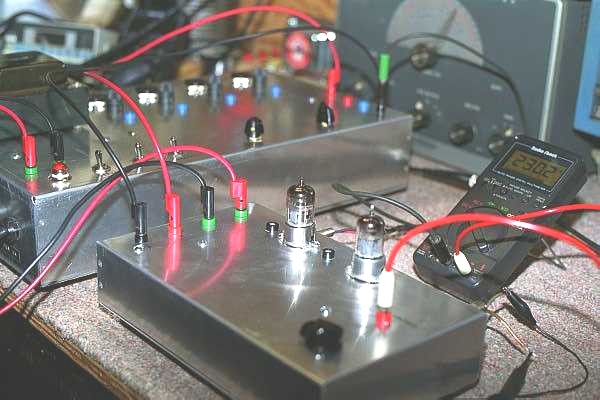
Have you every worked on a split chassis design? Some old amp models from Valco and even the later SVT's have the power amp enclosed in a separate chassis sitting at the bottom of the cabinet with the preamp enclosed in yet another chassis mounted to the top of the cabinet. So here's a typical situation with a split chassis design: you've just completed a restoration on the power amp which is now sitting on the bench. You power it up and all DC voltages look good. Now you reach for your signal generator to drive the power amp with an AC sine wave and you realize your signal generator only can drive 15v p-p. Not enough to drive the power amp into saturation. Actually 15v p-p is barely enough to drive a power amp at all. You look over where the cabinet contains the preamp sitting three feet away and realize that jumpering that 8 pin preamp to power amp umbilical cord is going to be impossible and dangerous. What you need is a preamp sitting on your bench that can drive a power amp's phase inverter into clipping so that power amp stressing can be observed on your scope and that power can be measured at the on-set of clipping.
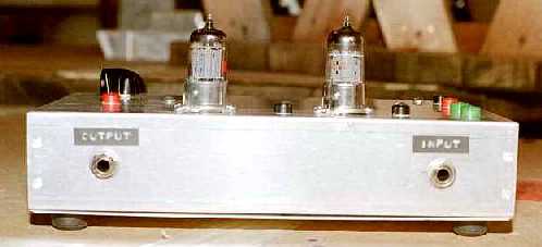
This design consist of three preamp gain stages and a cathode follower for low impedance driving when necessary. The gain structure is very similar to Fender and Marshall amplifiers without the tone controls. Most common 9 pin miniature dual triode preamp can be used such as: 12AX7, 12AT7, 12AY7, 12AU7 or any combination to achieve the required gain. To keep the design simple and the cost low, I'm using the power supply output capability of the DIY Tube Matcher also disclosed on this web site. All power amps from a split chassis design I've have seen thus far, contain the B+ power supply along with the heater supply. Thus when testing a split chassis power amp, by driving the power amp's phase inverter with the power amp driver, the B+ and heater supplies from the power amp can be used to power the power amp driver.
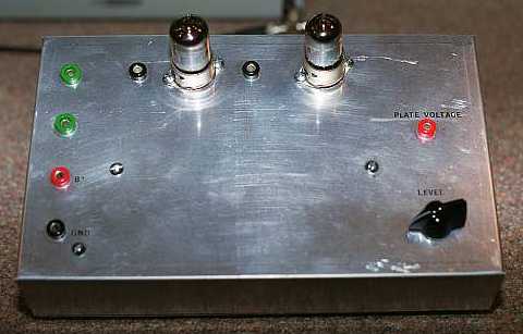
A second function of this preamp design is that it can also be used to test preamp tubes. Although a good mutual conductance tube tester is recommended and one should listen to a tube for it's sonic quality, this design has 1ohm 1% cathode resistors on the first preamp tube so cathode currents can be measured for triode DC balance. Although this measurement is not an absolute test for triode balance, it is however, an indication. The first gain stage plate voltage is also brought out to a banana plug which can be measured by a RMS volt meter or observed by an oscilloscope. Knowing the input voltage and measuring the plate voltage of the first stage, one can then calculate the gain and compare the gain to that of other preamp tubes. This same test point can also be used to set and monitor the DC plate voltage.
Hyper linked at the bottom of this web page are the schematic and parts list needed to built this design. A layout topology drawing will be posted soon.
| Concept |
| Parts List |
| Schematic |
| Layout |